Geometry Nodes Introduction
Geometry Nodes are a new way to model in Blender. You can use them to procedurally generate multiple objects simultaneously, modify them with small variations, and spread them around the mesh. Landscapes are a great use case. Blades of grass, gravel roads, fields of corn, etc.
If you’re a complete beginner, it’s now time to read less and do more. Open up Blender and make sure you’re version is 4.1 or higher.
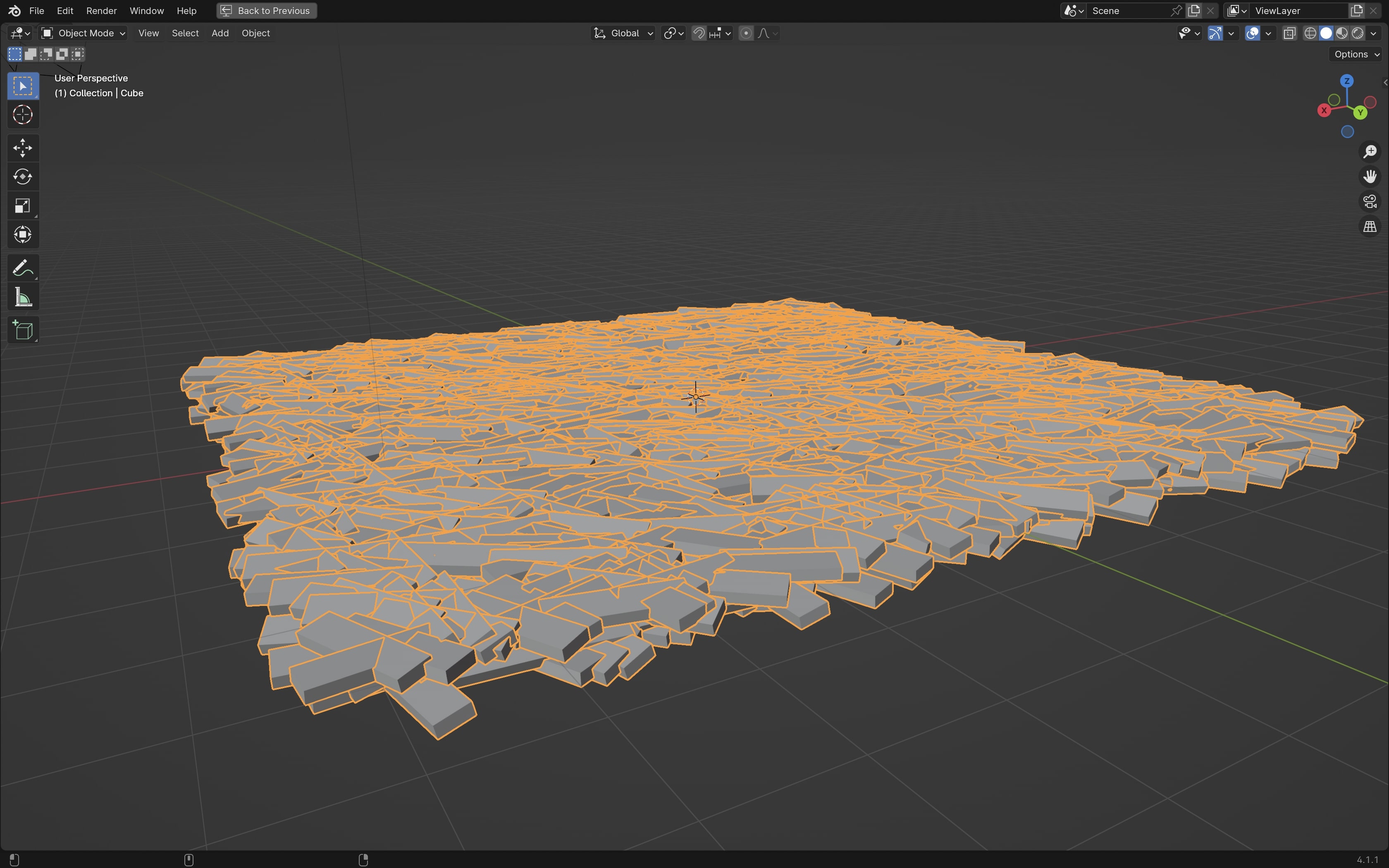
Mini Project: Build a floor of piled wood
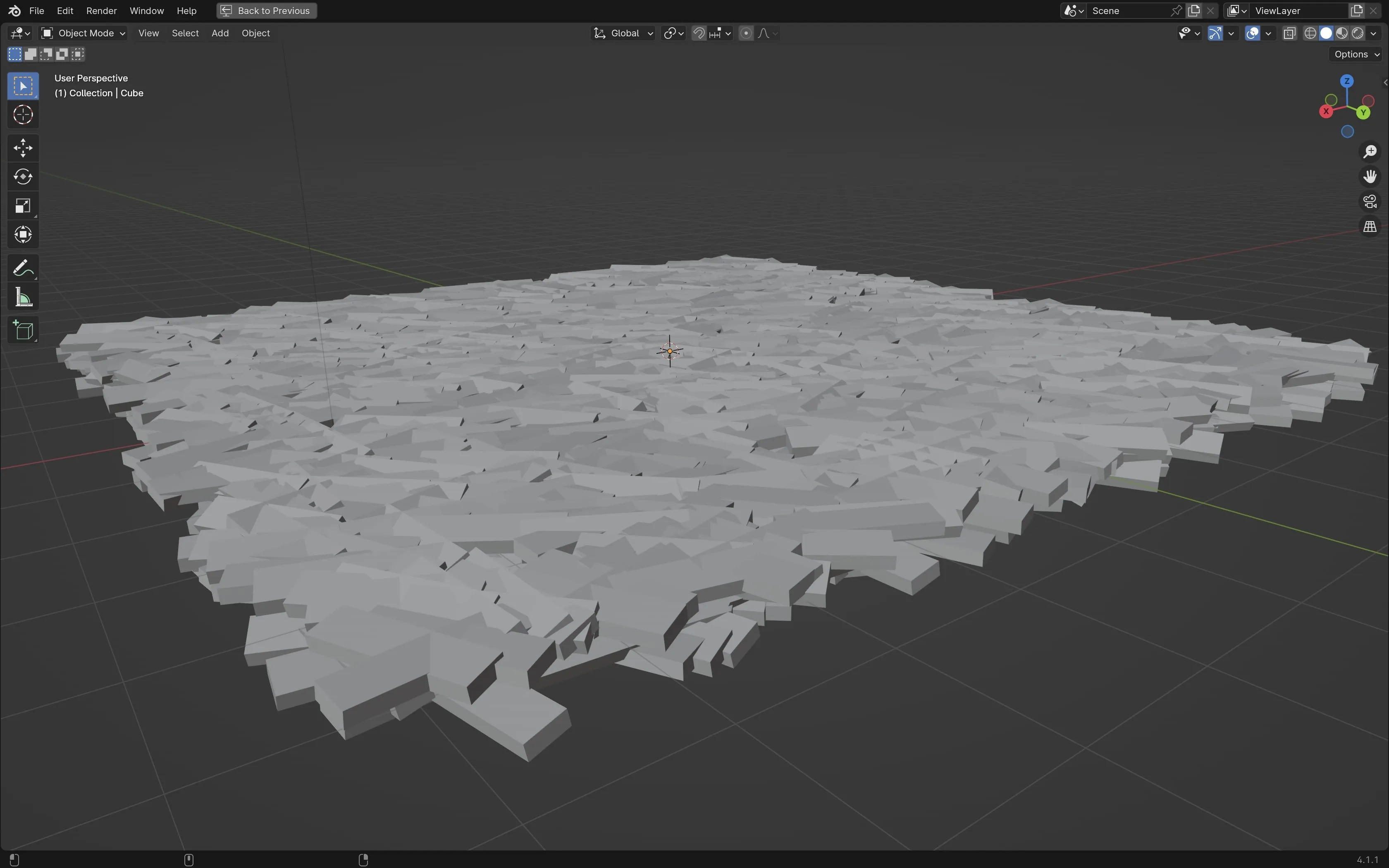 Note that I’ve ignored any materials, lighting, shading, etc so complete beginners can have a less confusing learning experience.
Step 1 - Your First Node
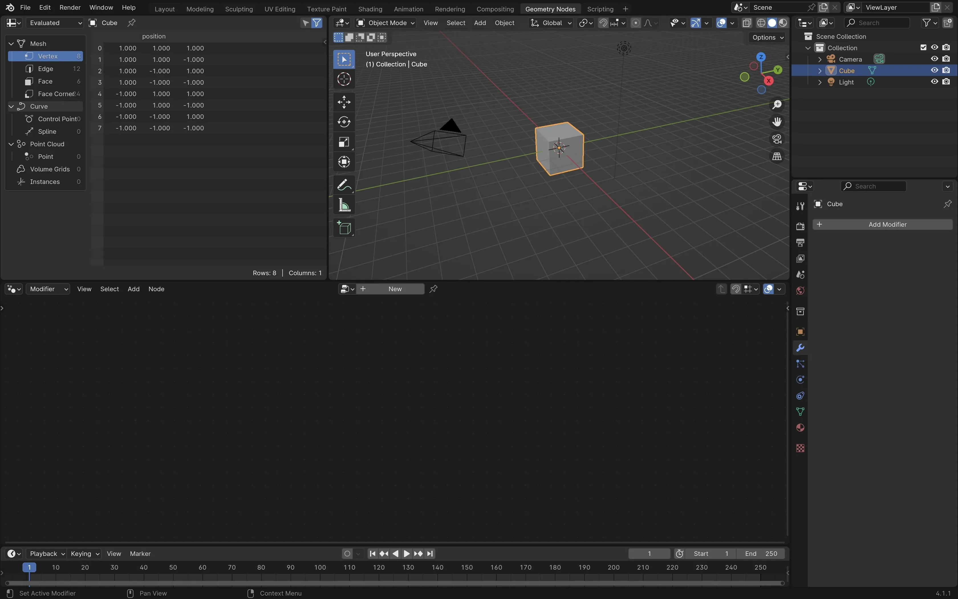
Open a new blender file. Find Geometry Nodes in the top navigation bar. Focus your attention on the bottom half of the screen. Ignore the Spreadsheet of numbers on the left.
Your first step is to click the ’+ New’ button on the bottom middle of the screen. This area is called the Geometry Nodes editor and it’s all you need to complete this tutorial.
Step 2 - Connecting your nodes
Two nodes called ‘Group Input’ and ‘Group Output’ are connected with a line between them. Grab the line and drag it to disconnect them. Your cube will disappear. Why?
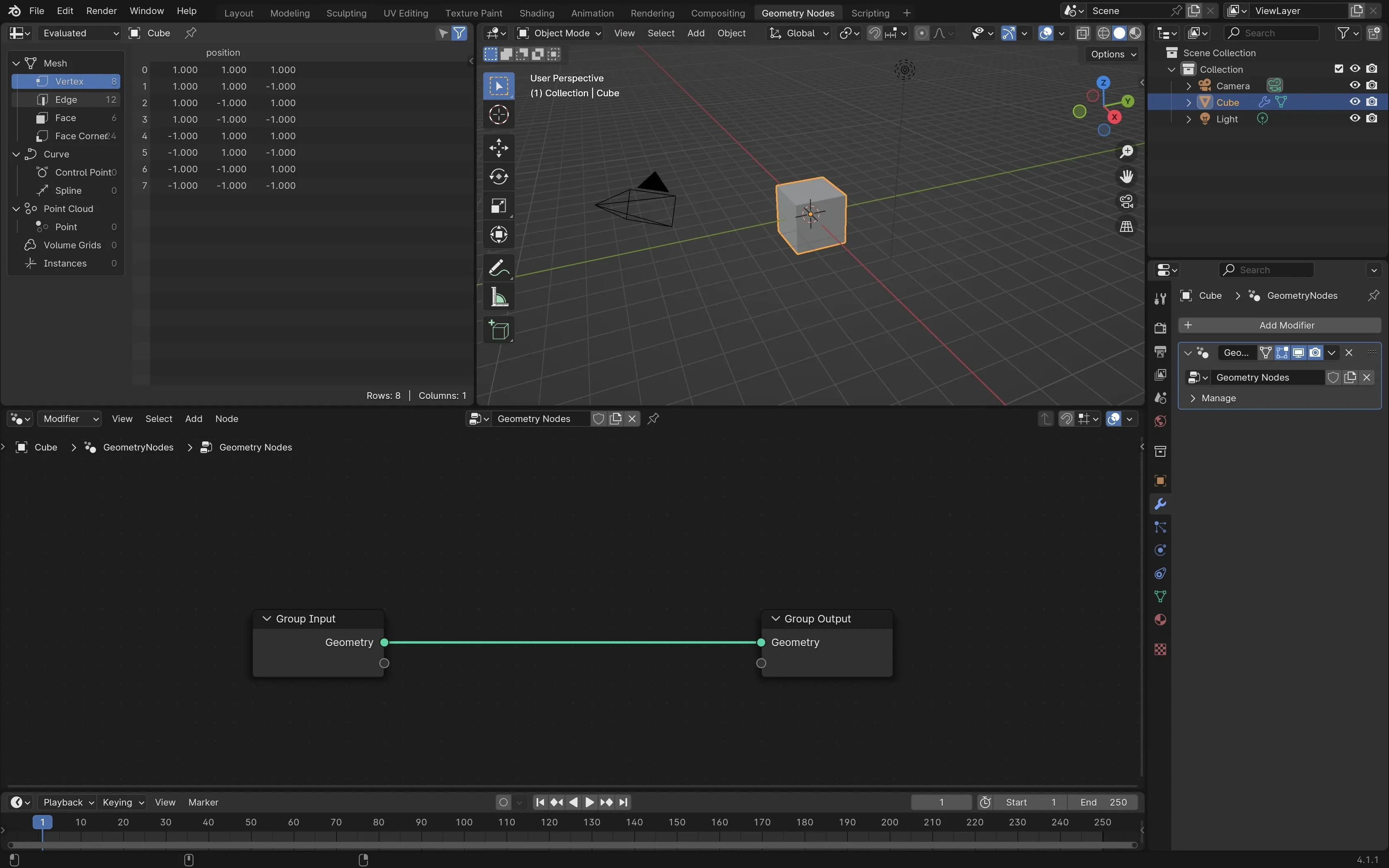
Think of this line as a pipeline or conveyor belt for changing your cube. The ‘Group Input’ is the entrance and the ‘Group Output’ is your final result. When you click that ’+ New’ button, your cube is modified to display based on the results from ‘Group Output’.
The cube will not look any different because you’ve made no modifications between the two group inputs. Let’s add a new node to start changing the cube.
Step 3 - Modify your cube into a floor using Geometry Nodes
You need to add a new node between the ‘Group Input’ and ‘Group Output’ of the Geometry Nodes editor. The ’+ New’ button is no longer clickable.
To add a new node, press ‘Shift A’. In the search bar, type “Transform Geometry” and press enter. Drag the ‘Transform Geometry’ node between the two group inputs. If your lines are all connected, the cube will reappear unchanged.
On the ‘Transform Geometry’ node properties, you’ll see three sections with circles beside them for Translation, Rotation, and Scale. Change the scale values for X, Y, and Z to 5, 5, and 0.1 respectively.
If this is your first time using Geometry Nodes, congratulations on modifying your first object using procedural generation.
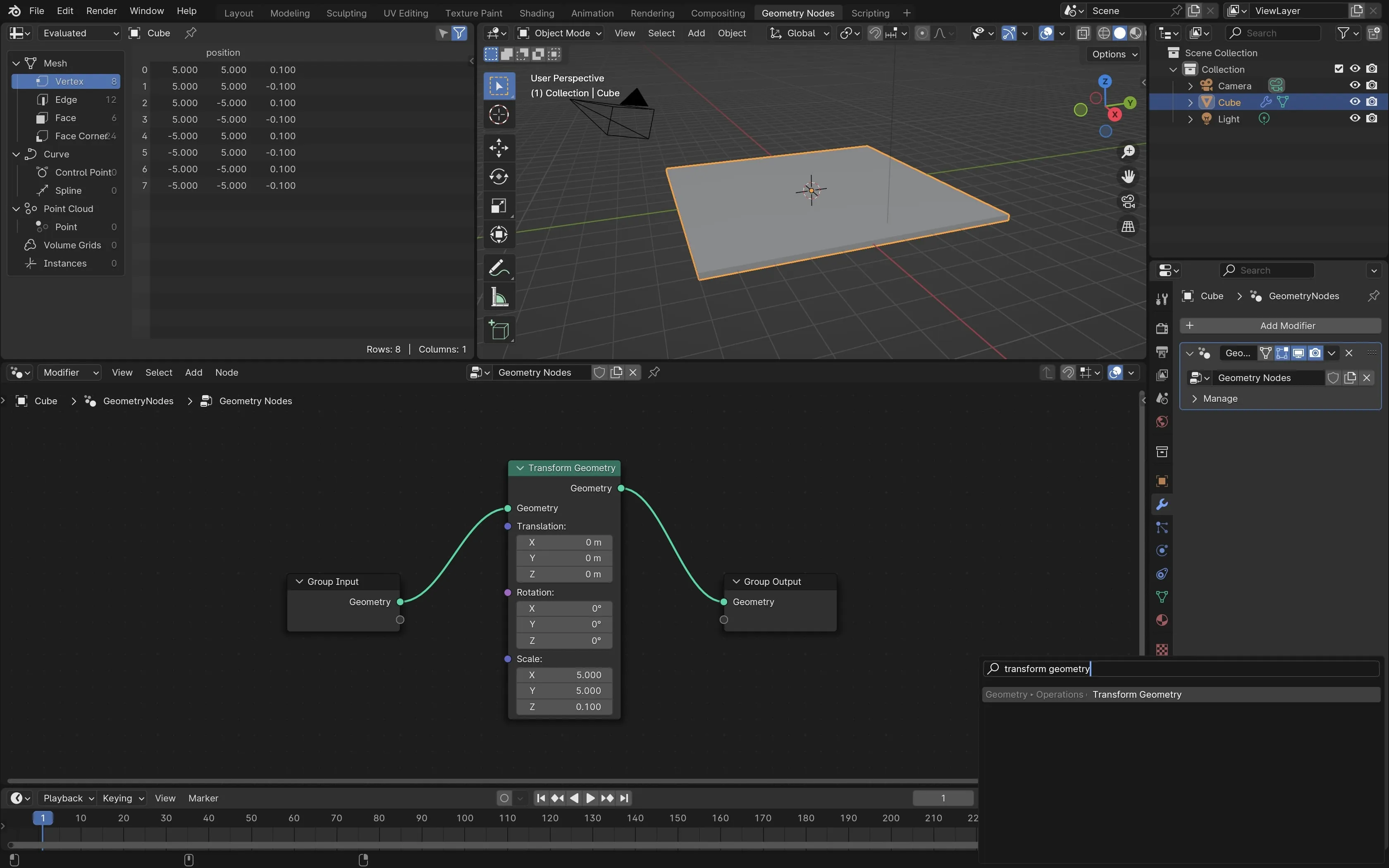
So what’s happening here? To turn a cube into a floor, you first scaled the cube on the X and Y axis to five times the original size. The Z value represents the height and you reduced the height of the cube to only 10% of the original size so it appears flatter.
Step 4 - Transform your cube into a point cloud
This is the first step to breaking up your floor into procedurally generated randomness. You have your floor but it’s flat and smooth. Let’s take your floor it break it into hundreds of pieces.
Press ‘Shift A’ to add a new node and type ‘Distribute Points on Faces’ and press enter. Add this node between the ‘Transform Geometry’ and ‘Group Output’. You’ll now see a cloud of randomly distributed points in the shape of your floor.
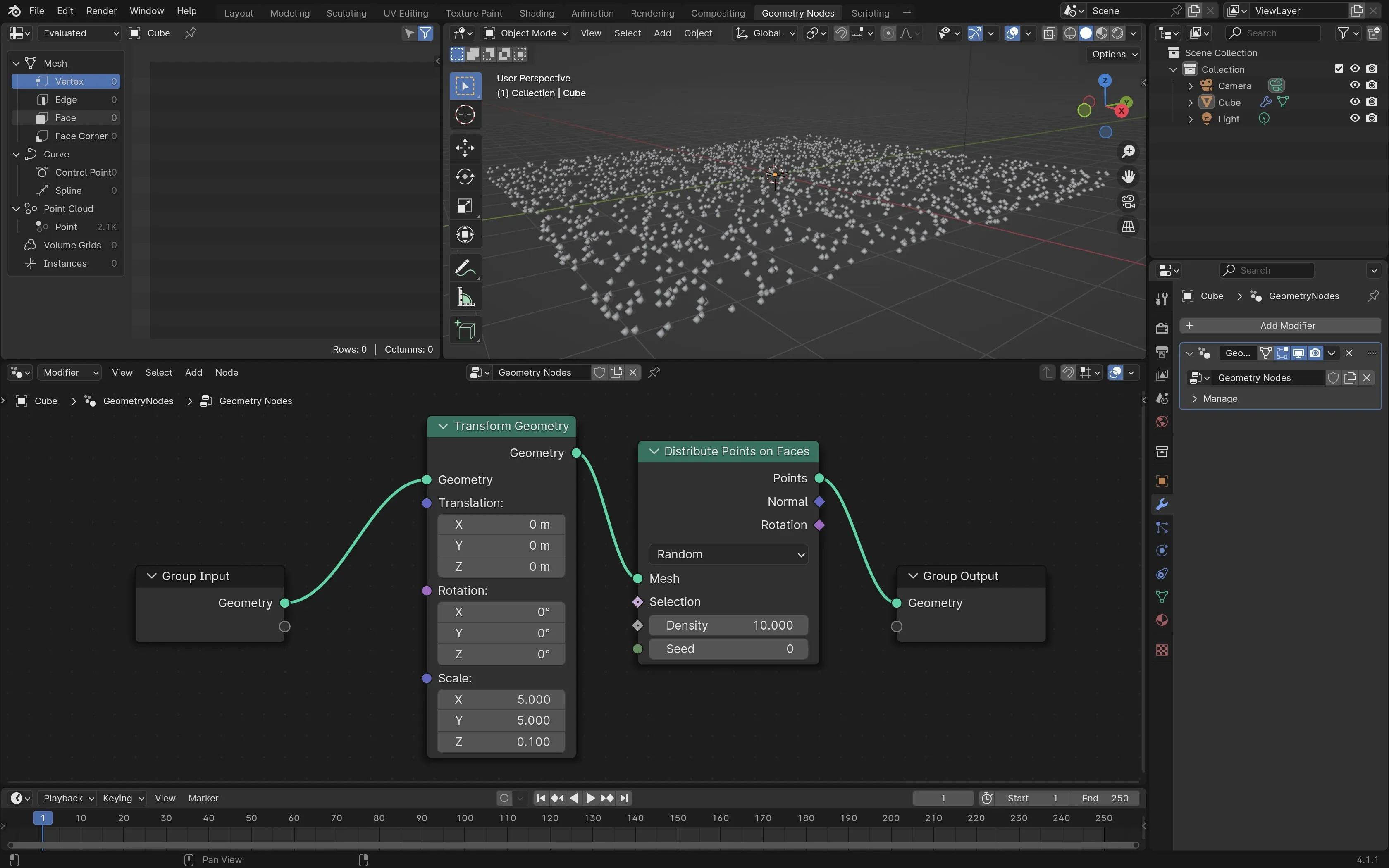
What’s the point of a point cloud?
A point cloud randomly distributes points in the 3d space. The points are only distributed inside the boundaries of your original object whether it’s cube or a sphere. Creating a point cloud is the first step to procedurally generating random changes to an object.
Each point can be modified independently and then rebuilt. You can reduce the amount of points by changing the ‘Density’ from 10.000 on the ‘Distribute Points on Faces’ node to 5 or 1. The more points you add, the more clearly you can see the original shape of the object. Set the density back to the default value of 10.000 if you changed it.
To make changes to each point individually, you need to add a new node.
Step 5 - Make a cloud of cubes
Press ‘Shift A’ to add a new node, type ‘Instance on Points’ and press enter. Place the node between ‘Distribute Points on Faces’ and ‘Group Output’. Both the cube the cloud of points have now disappeared.
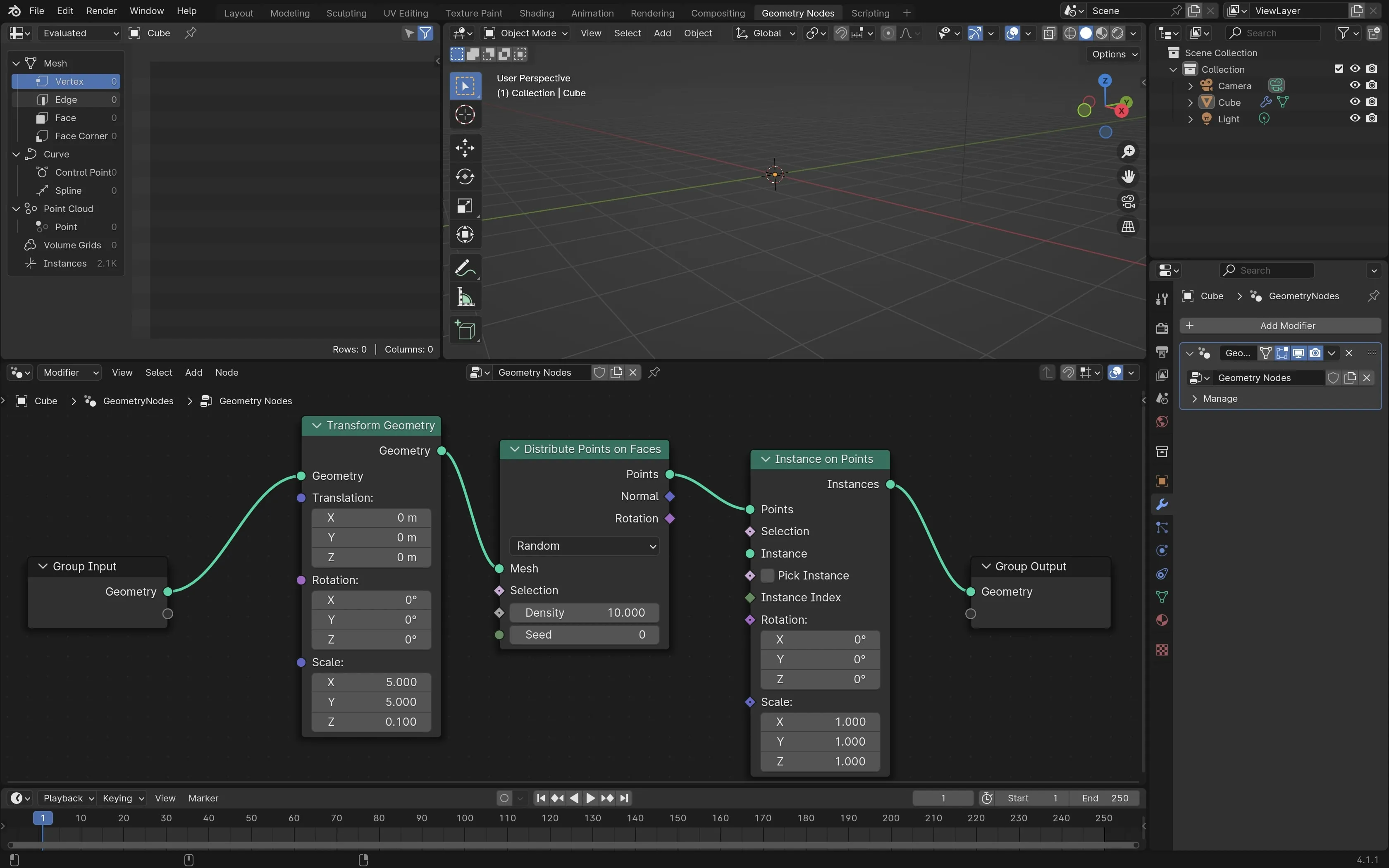
Why did the cube disappear even though the line is connecting all nodes?
Every point in the cloud is now an instance. Think of an instance as a location stored in memory. Right now, each dot of your original point cloud is a coordinate in 3d space of which you can assign new objects.
The cube disappeared because no visible objects are assigned to the coordinates of your point cloud. To make your your visible again, let’s generate a new cube at every location in the original point cloud.
You need to assign an object to the ‘Instance’ section under the ‘Instance on Points’. You can do that by dragging on the green circle to make a new node. You can also press ‘Shift A’ connect them manually. Type in ‘Cube’ and hit enter.
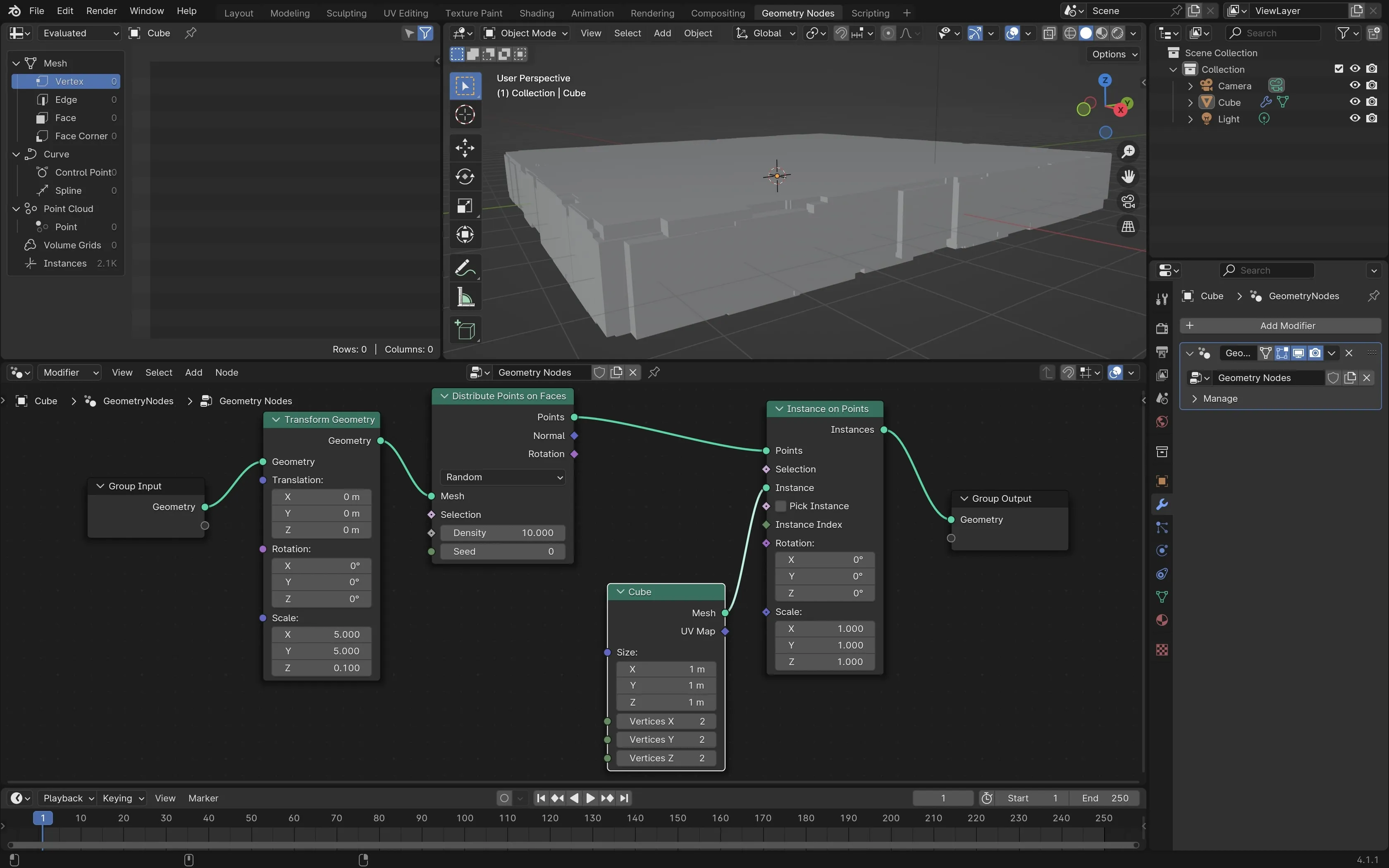
Congratulations, the hard part is over. You now have a procedurally generated floor with randomized jagged edges. Before moving on to the final step, ask yourself these questions:
- Why are the sides of the floor jagged?
- Why is the top of the floor so smooth?
- Can you reduce the size of the cubes to make a cube cloud?
The floor looks solid because the point cloud you created is now a cloud of overlapping cubes. Although the cubes can overlap each other, they can’t expand outside the border of the original floor you created. 5 meters on the X and Y axis. 0.1 meters on the Z axis.
Your cloud of points are now instances and every instance has a cube. Reduce the size of the instance cube on the X, Y, and Z axis to 0.1 meters. There is now space between each cube and you can see the cloud shape again.
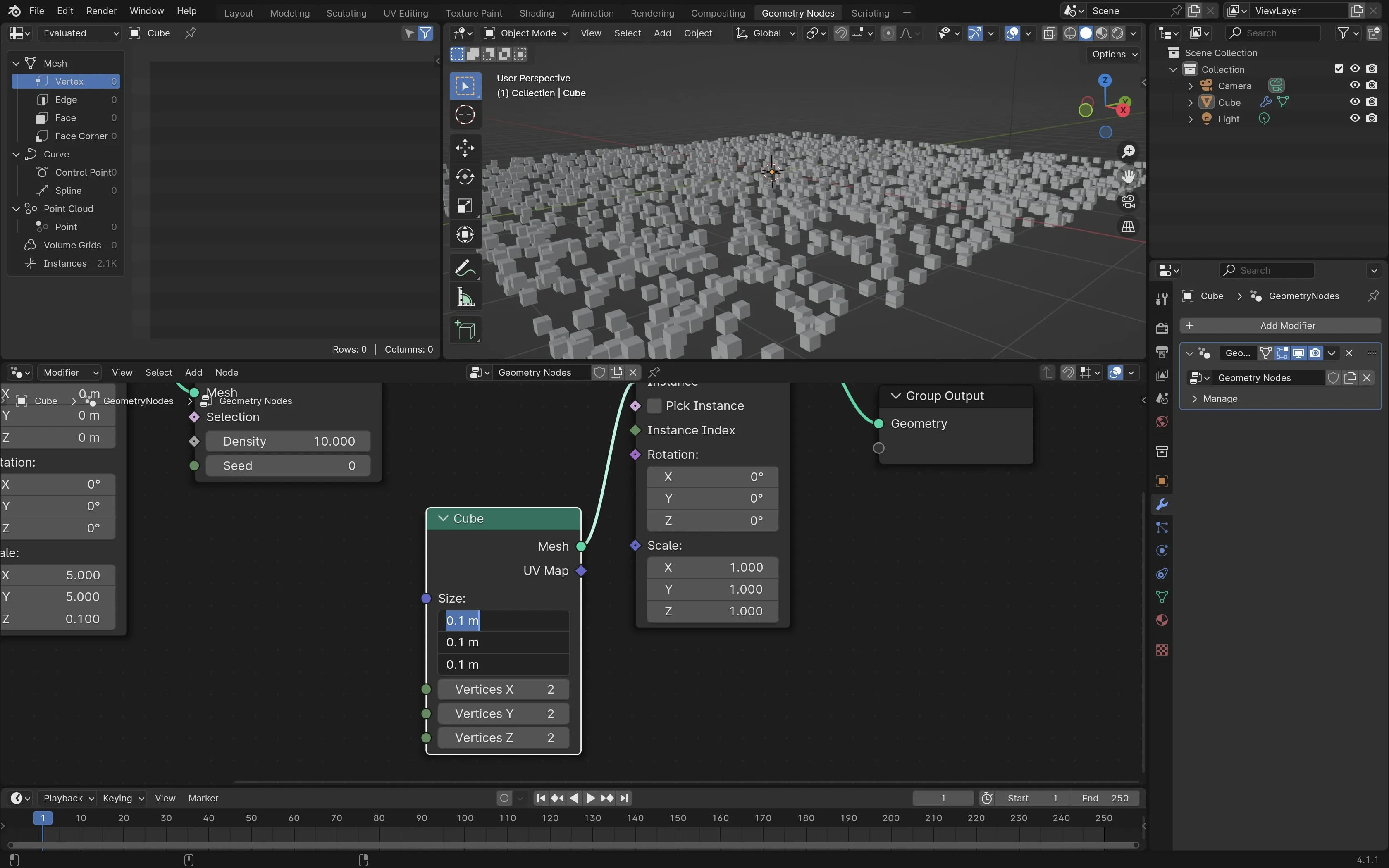
Final Step - A pile of wood planks
Before start, make your floor solid again. Also, the height of the floor is much higher than before so reduce it back to your original dimensions. Simply change the values of the ‘Cube’ node to 1m on the X and Y axis and 0.1 on the Z axis.
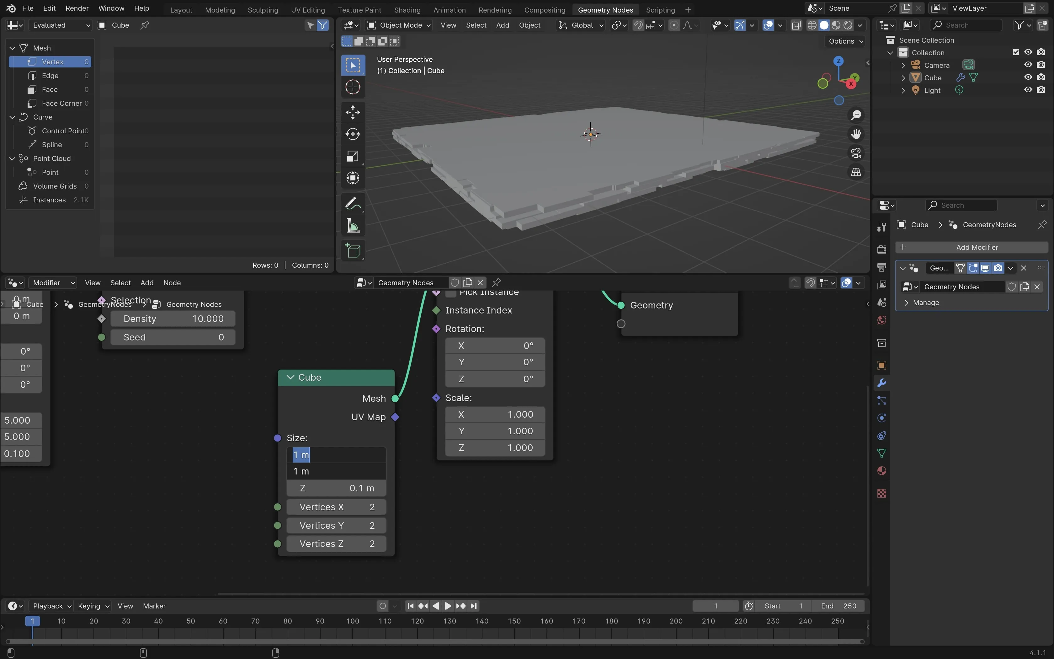
The floor is very flat on top because the rotation of every cube is facing the same direction. Can you change the direction all the cubes? Find the ‘Instance on Points’ node and look at the Rotation section. The values of X, Y, and Z are all set to 0 degrees. You can see how all the cubes rotate together as you change the values.
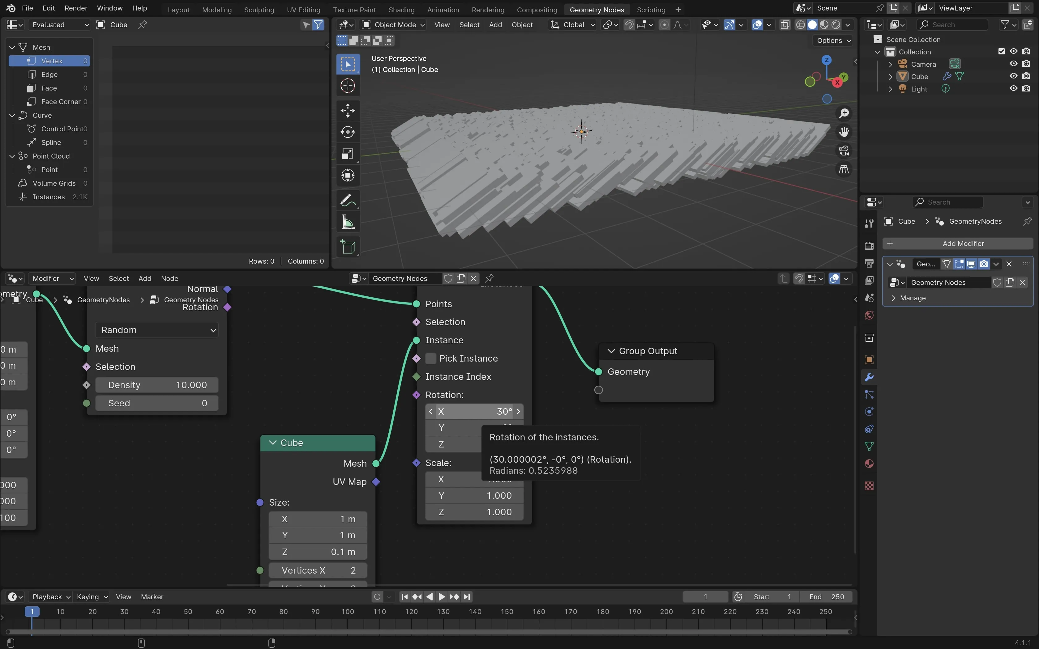
Changing the rotation of the cubes looks cool but it’s still very uniform. Right now, you’re setting the same degrees of rotation for every cube. The final step is to add a random number to the rotation. To make every cube face a random direction, you need one last node to complete the tutorial.
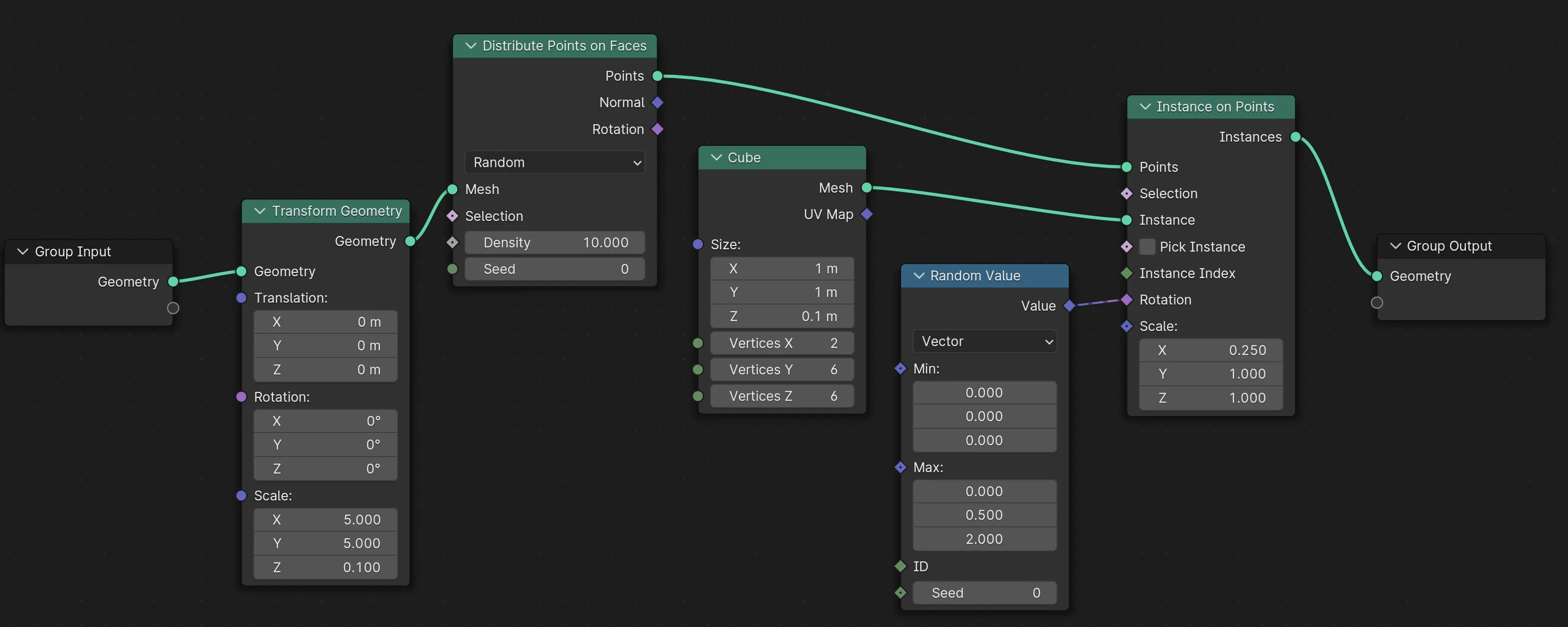
Press ‘Shift A’ and add a new node called ‘Random Value’. Connect this node to the Rotation section in the ‘Instance on Points’ node. On the ‘Random Value’ node, click the dropdown and change it from ‘Float’ to ‘Vector’. You do this because you need a random value for every axis.
You now have a ‘Min’ and a ‘Max’ section in your ‘Random Value’ node. The three numbers in each section correspond to the XYZ coordinates. Set Min to 0,0, and 0. Set the Max to 0, 0.5, and 2,0.
Every cube now has a random value of rotation. Truly random wouldn’t look as realistic. Piles of wood in real life are still restrained by gravity. By setting the min and max values, you limit the range of random rotation values to a specific range.
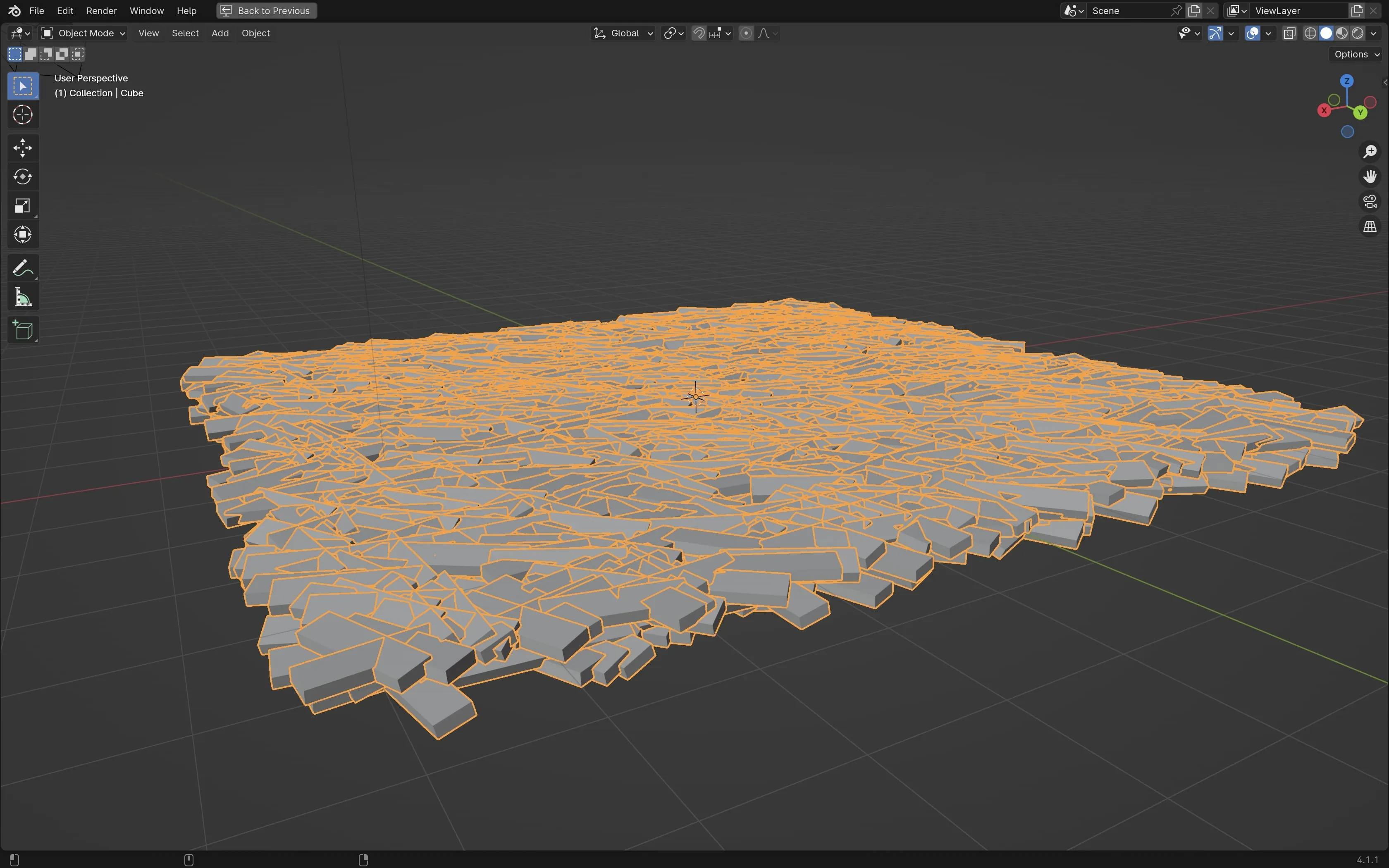
Finally, change your random pile of squares to look more like planks of wood. On the ‘Instance on Points’ node, change the scale of X to .25. Here’s my final node setup for you to compare:
Final Result:
Download the .blend file using this link: (coming soon).