Geometry Nodes - Simulation Nodes Introduction
In our last post[link], we learned how to use Geometry Nodes to turn a cube into a pile of wood. What if you wanted to simulate the smoke rising from setting that pile of wood on fire? Sounds complicated for a complete beginner. Let’s make the problem simpler.
Before you can make smoke rise in the air, can you make the default cube rise into the air? This tutorial will teach you how to simulate movement using Geometry Nodes.
Step 1 - Setup
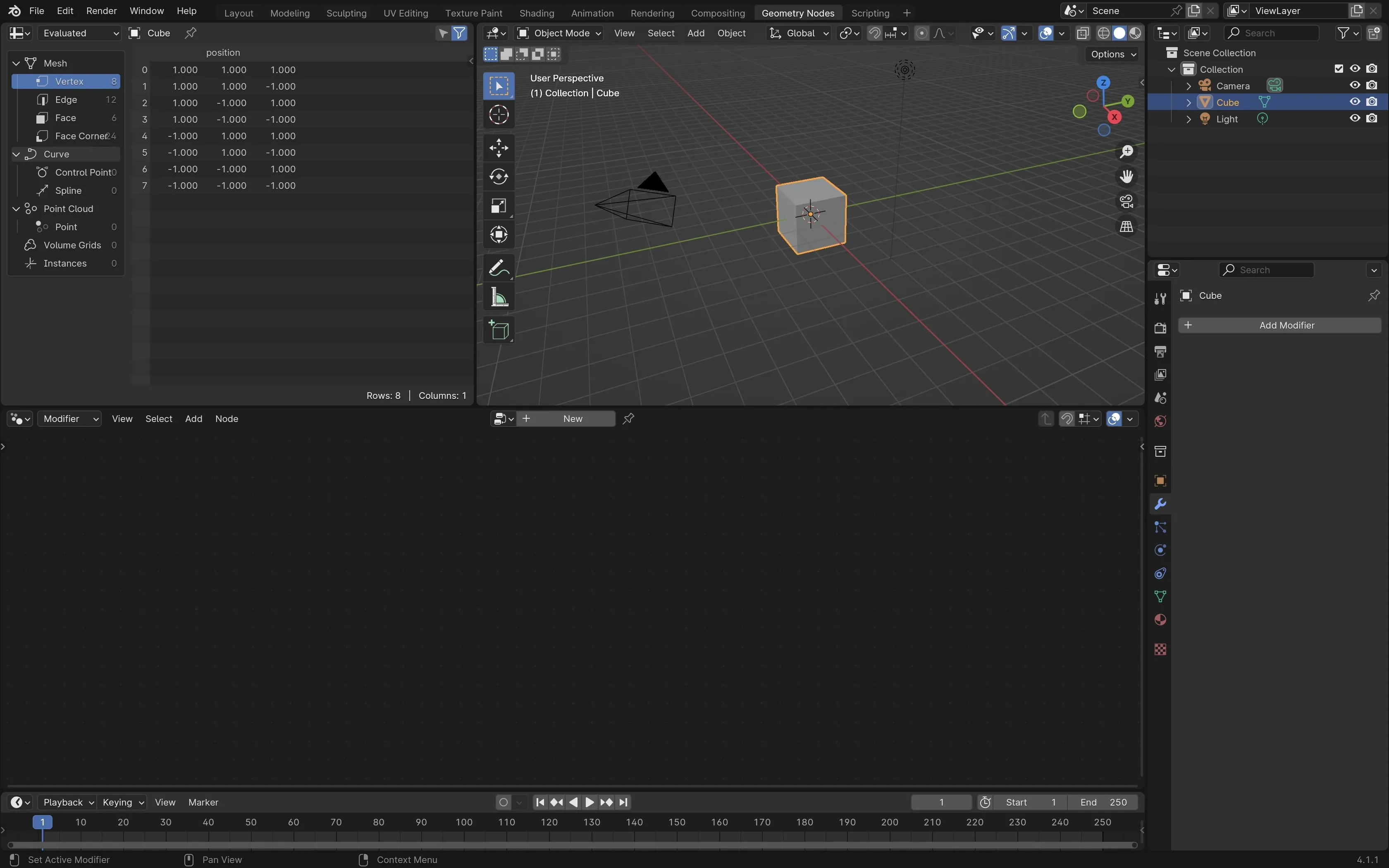
Open a new blender file. Find Geometry Nodes in the top navigation bar. Click the ’+ New’ button on the bottom middle of the screen.
You will see two nodes called ‘Group Input’ and ‘Group Output’ connected by a line. Your default cube should still be visible. If you disconnect that line, the cube will disappear.
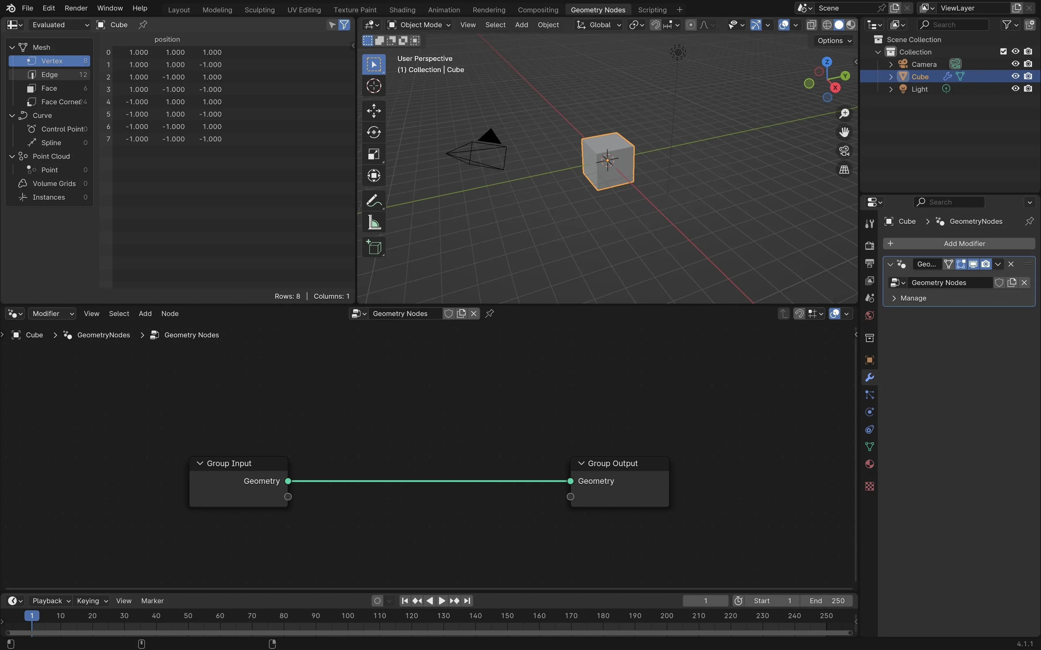
If you remember from the last post, when you create a new Geometry Node, you modify the original cube to display based on the results of the ‘Group Output’. To make the cube move, we need to add a new node.
Step 2 - Your first simulation node
Before adding a new node, drag one of the group nodes to make them farther apart. This will give you more room. Disconnect the group inputs and you’ll see your cube disappear.
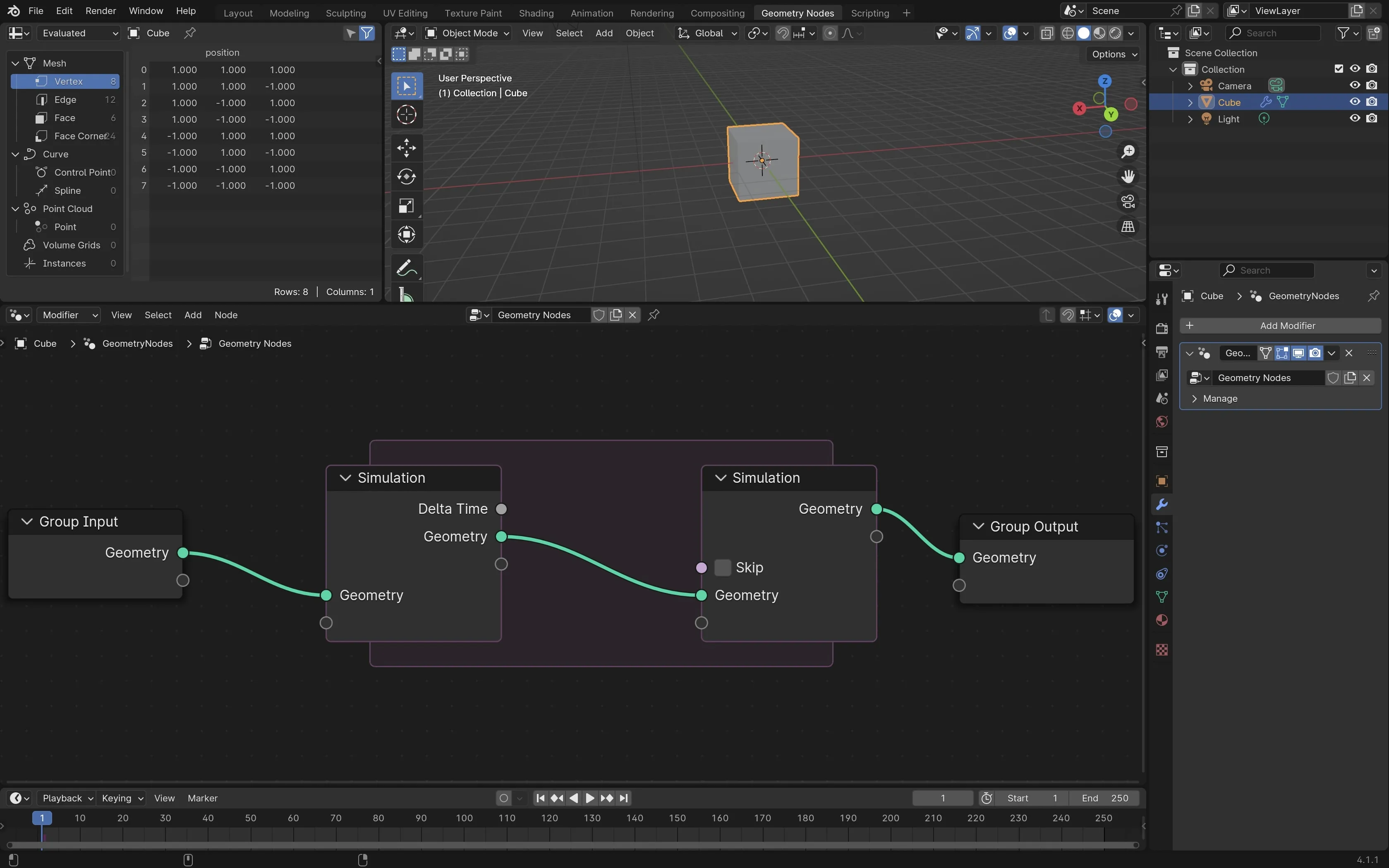
Now press ‘Shift A’ and type ‘Simulation Zone’. You’ll see two new simulation nodes connected by a box. Place them between your original group inputs
On the ‘Group Input’ node where it says ‘Geometry’, click on the green circle and connect it to the first ‘Simulation’ node. On the second ‘Simulation’ node, connect the green circle to the ‘Group Output’ node. Your cube should now be visible again.
Step 3 - Adding velocity
Each of the simulation boxes only have two values currently: ‘Delta Time’ and ‘Geometry’. We need to add a new value called velocity so we can tell Blender how fast to move the cube. Inside the Geometry Nodes editor, click on view and click sidebar. You can also press ‘N’. You will now see a panel on the right.
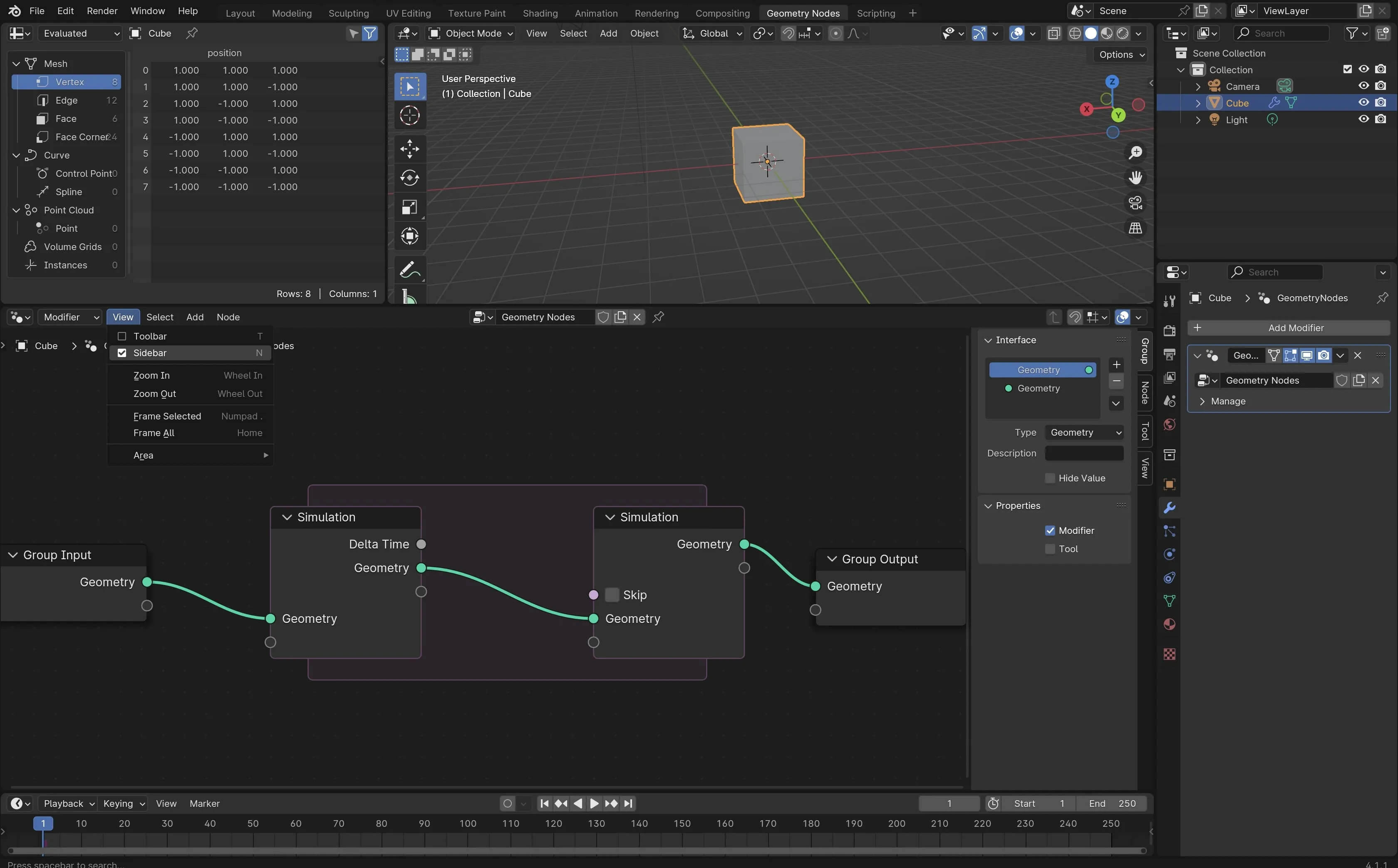
We want to add a ‘State Item’ to the node. On the far right of the sidebar, you will see four tabs. Click on the second tab called ‘Node’. Under a section called ‘Simulation State’, there is a plus sign. Click that button to add a state item.
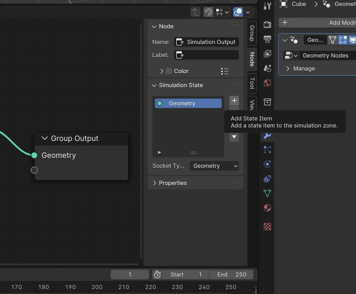
Click on the new state. Rename it to ‘Velocity’. Find the dropdown beside ‘Socket Type’ and change it from ‘Geometry’ to ‘Vector’.
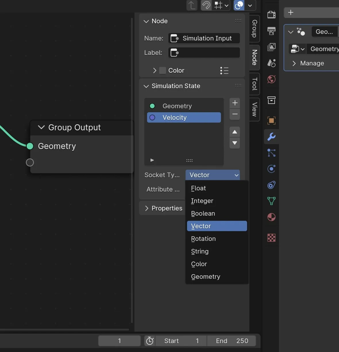
There is now a ‘Velocity’ option in blue on both simulation boxes. Connect the velocity option. Nothing moves yet. In order to make the cube move, you need to connect the velocity to a ‘Set Position’ node.
Step 4 - Making the cube rise
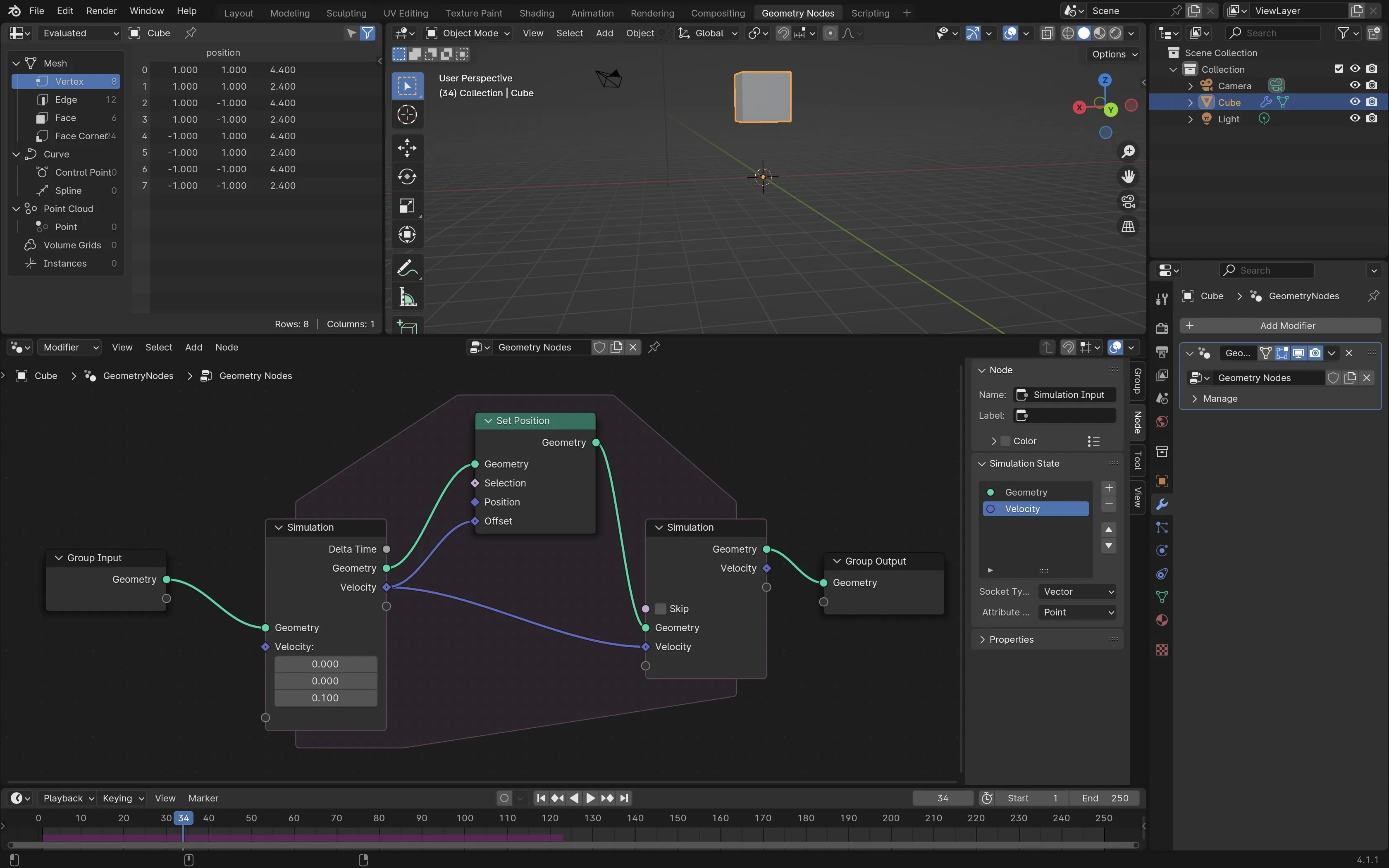
Press ‘Shift A’ to add a new node and type ‘Set Position’. Connect the Velocity from ‘Simulation Input’ to Offset on the ‘Set Position’ node. Nothing happens yet because we have not specified the direction or the speed for the cube to move.
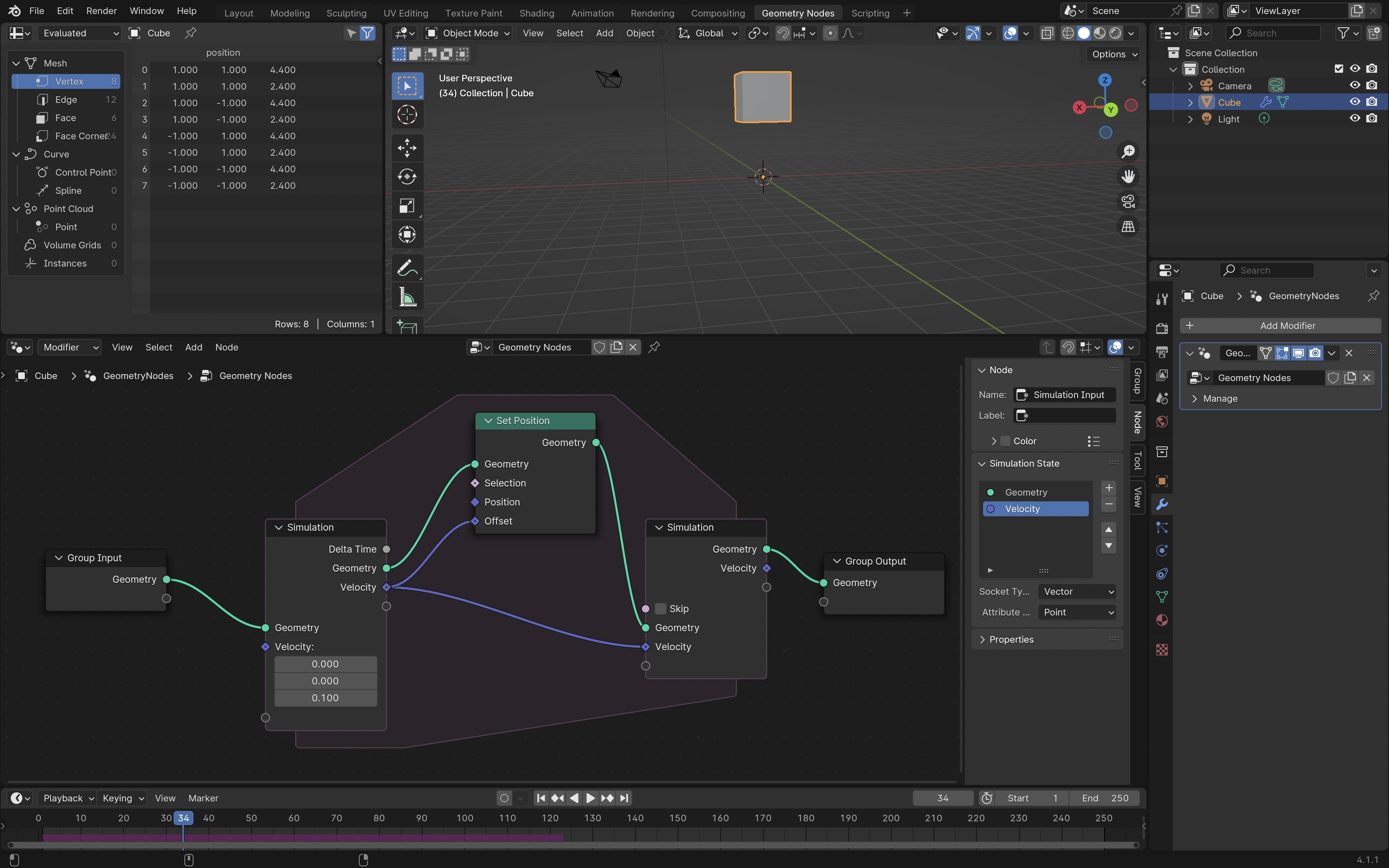
To make the cube rise in the air, we need to make it move along the z-axis. Under the Velocity section for ‘Simulation Input’, change the Z value to 0.1. If you press spacebar, you should now see the cube rise. Here is the final node setup:
Final Notes
To reset the position of the cube, drag the blue player at the bottom back to 0. Pressing spacebar is a shortcut for press play. Your cube will rise for 250 frames before looping back to the beginning state. You can change the number from 250 to a lower value if you want a shorter loop.